
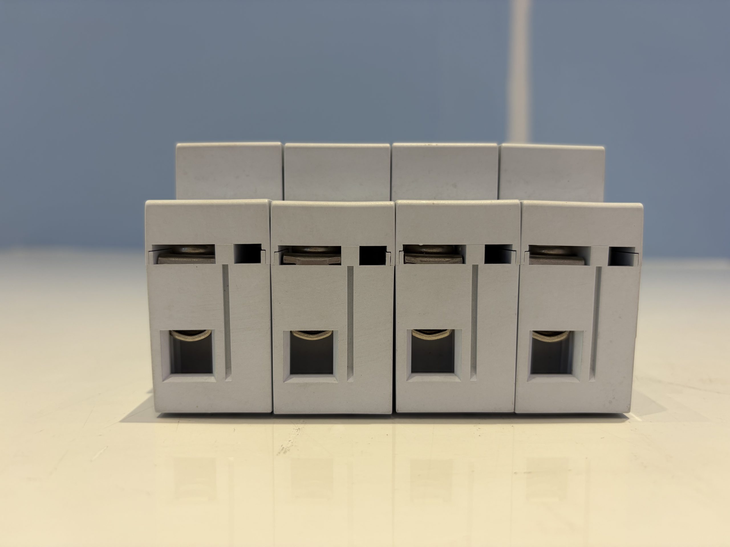
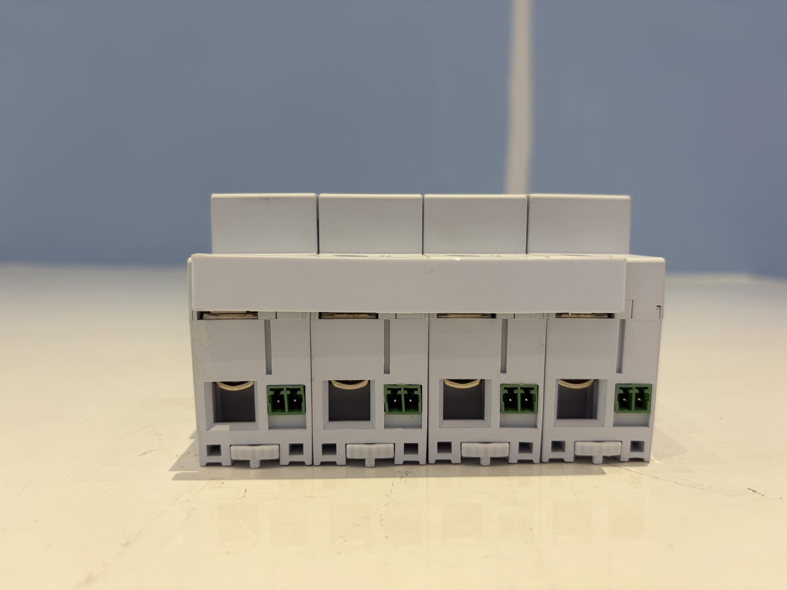
GBV-120-385-3+1-27 AC Power Surge Protective Device, Class II, 120 kA Imax
Request a quote
Quality & certifications
Description
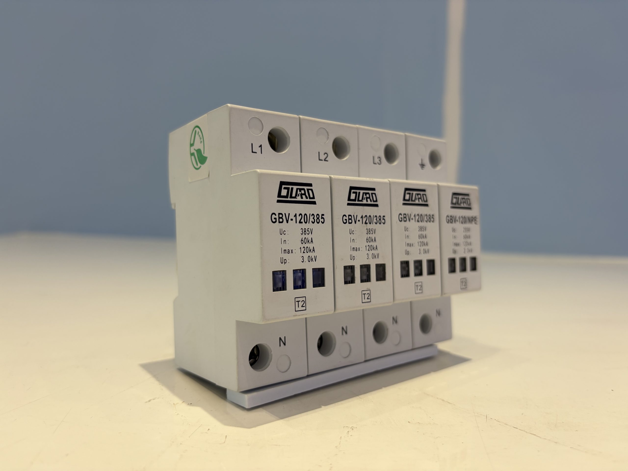
The GBV-120-385-3+1-27 is a Class II AC power surge protective device intended for lightning overvoltage protection of single-phase AC power supplies. It limits transient overvoltages at the L-N and N-PE paths and provides a status indicator together with a remote signalling contact for monitoring.
Product Overview
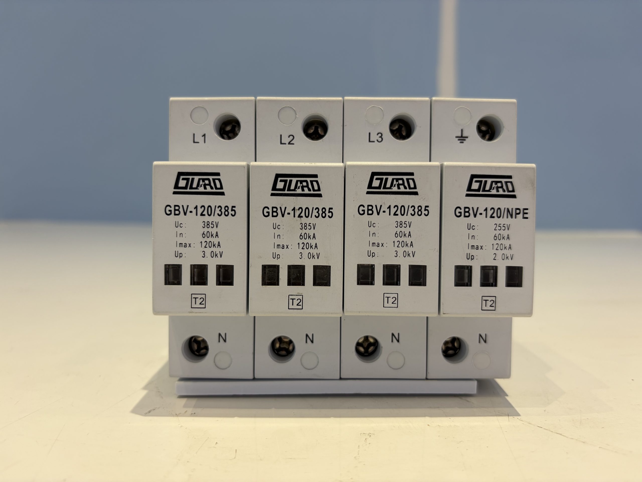
The device is designed for single-phase AC supply protection at Class II. Its nominal operating voltage Un is 220V~, with a maximum continuous operating voltage Uc of 385V~ across L-N and 255V~ across N-PE. Surge current capability is specified as In 60kA and Imax 120kA, with voltage protection levels of 3.0kV (L-N) and 2.0kV (N-PE) measured at In with an 8/20µs waveform.
Key Features
- Class II surge protection for single-phase AC power supplies
- L-N and N-PE protection paths with separate voltage protection levels
- Nominal discharge current In 60kA and maximum discharge current Imax 120kA
- Fast response: tA 25ns (L-N) and 100ns (N-PE)
- Status indicator window: white for normal operation, red for failure
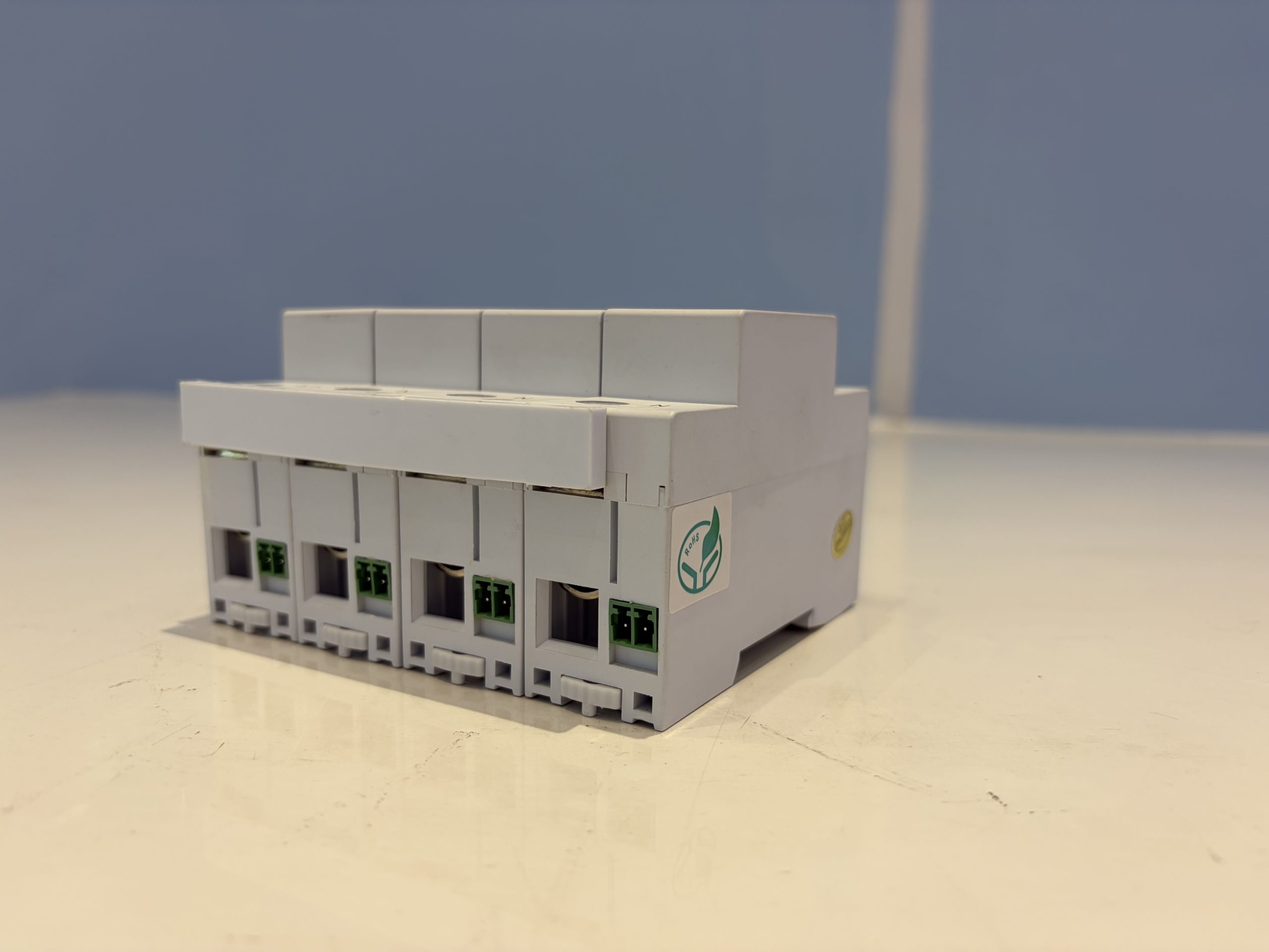
- NC-COM changeover remote signalling contact
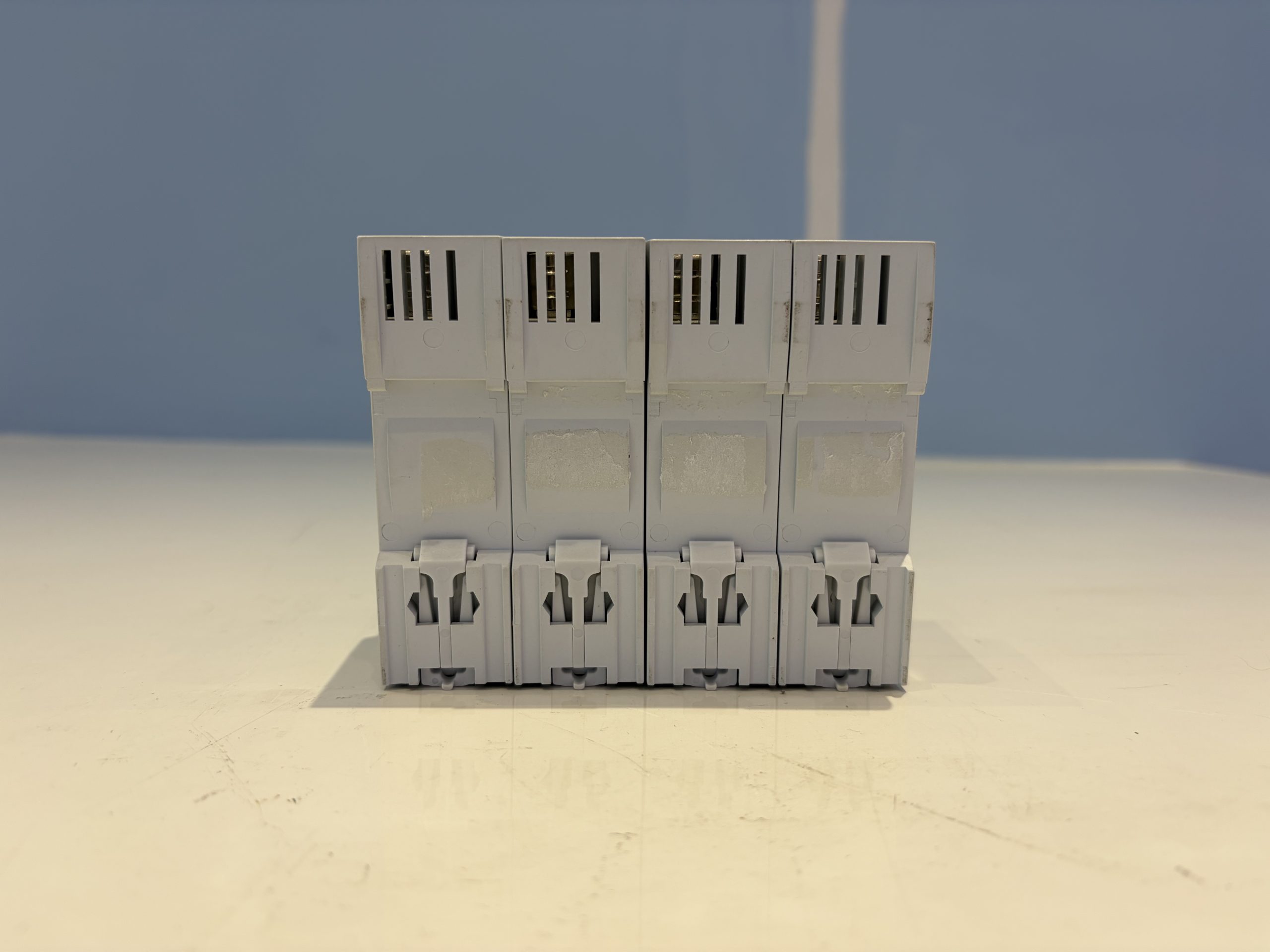
- 35 mm DIN rail mounting
- PBT enclosure with UL94-V0 flammability rating and IP20 protection
Technical Specifications
| Parameter | Value |
|---|---|
| SPD classification | II |
| Nominal operating voltage Un | 220V~ |
| L-N maximum continuous operating voltage Uc | 385V~ |
| N-PE maximum continuous operating voltage Uc | 255V~ |
| Nominal discharge current In | 60kA |
| Maximum discharge current Imax | 120kA |
| L-N voltage protection level Up (In@8/20µs) | 3.0kV |
| N-PE voltage protection level Up (In@8/20µs) | 2.0kV |
| L-N response time tA | 25ns |
| N-PE response time tA | 100ns |
| L-N, N-PE status indication | White: normal / Red: failed |
| Mounting method | 35mm DIN rail |
| Conductor connection capacity | ≤35mm² |
| Maximum torque | 3.5Nm~4.5Nm |
| Enclosure material | PBT |
| Enclosure flammability rating | UL94-V0 |
| Enclosure protection rating | IP20 |
| Remote signalling contact type | Changeover contact, NC-COM normally closed |
| Remote signalling contact AC rating | 250V/0.5A |
| Remote signalling contact DC rating | 125V/0.2A |
| Remote signalling contact terminal capacity | ≤1.5mm² |
| Temperature and humidity range | -40℃ to +80℃, relative humidity ≤95% |
| Altitude | ≤3000m |
| Main body dimensions | 90mm×65mm×54mm |
Applications
The GBV-120-385-3+1-27 is used for Class II lightning overvoltage protection of single-phase AC power supplies. It is suitable for installation in AC power distribution equipment where L-N and N-PE surge protection is required.
Installation and Use
The device can be connected using conventional direct parallel wiring or V-shaped wiring. For better protection with direct parallel connection, wiring should be as short as possible, with total length controlled within 0.5m. Connecting conductors should be 25-35mm² multi-core copper cable.
A suitable circuit breaker or fuse must be connected in series ahead of the SPD; the circuit breaker should use C trip characteristics. Power must be disconnected during installation; live operation is strictly prohibited, and connecting conductors must meet the specified requirements.
During normal operation, the status indicator window is white and the NC-COM alarm dry contact is in the conducting state. When the SPD fails, the status indicator turns red and the NC-COM alarm dry contact becomes open. The SPD requires no special maintenance; only periodic checks of module tightness and status indication are needed.
The SPD should be replaced promptly if either of the following occurs: the status indicator turns red, or the alarm dry contact becomes open.
Frequently Asked Questions
What does the status indicator show?
White indicates normal operation; red indicates the SPD has failed and should be replaced.
How is the remote signalling contact configured?
It is a changeover contact with NC-COM normally closed. It conducts during normal operation and opens when the SPD fails.
What conductor size is required?
Connecting conductors should be 25-35mm² multi-core copper cable, and the terminal connection capacity is ≤35mm².
What is the maximum wiring length for parallel connection?
When using direct parallel wiring, total length should be controlled within 0.5m.
Related products
-
G1V-80/385/B+C FM Three-Phase AC Power Surge Protection Device, Class II, 80 kA Imax
Request a quote -
GCV-40-385-3+1 FM Three-Phase AC Power Surge Protective Device, Class II, 40kA Imax
Request a quote -
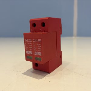
GCV-40/385/2 FM AC Power Surge Protective Device, Class II, 2-Pole, 40kA Imax
Request a quote -
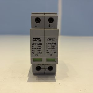
GCV-60/385/1+1 Single-Phase AC Power Surge Protective Device, Class II, 60kA Imax
Request a quote
Reviews
There are no reviews yet.