
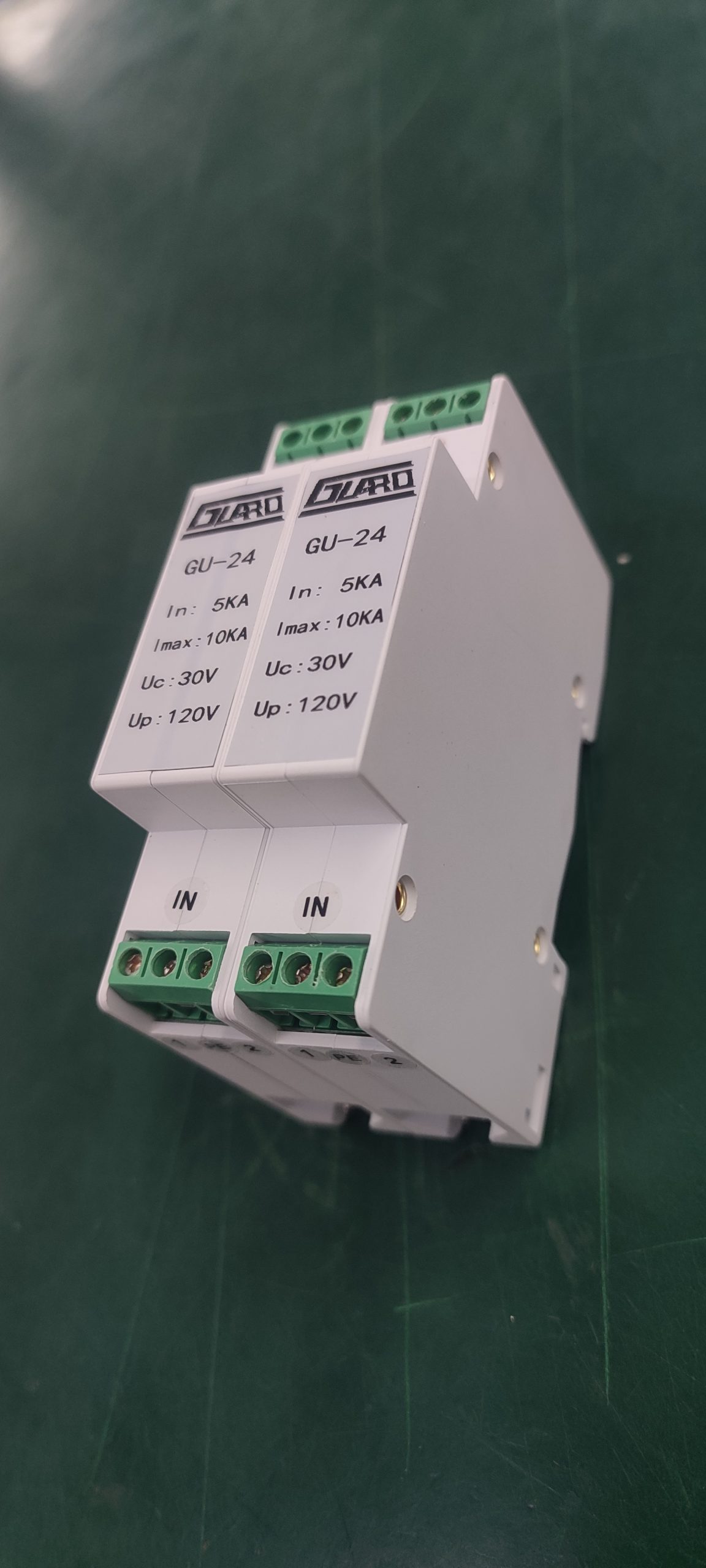
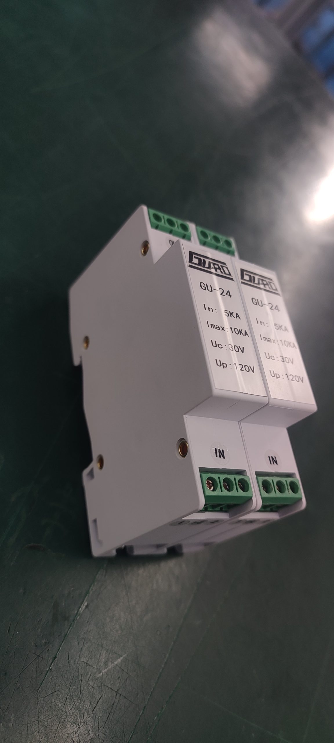
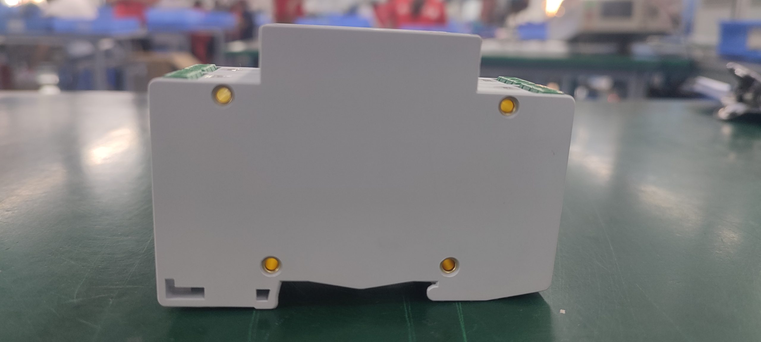
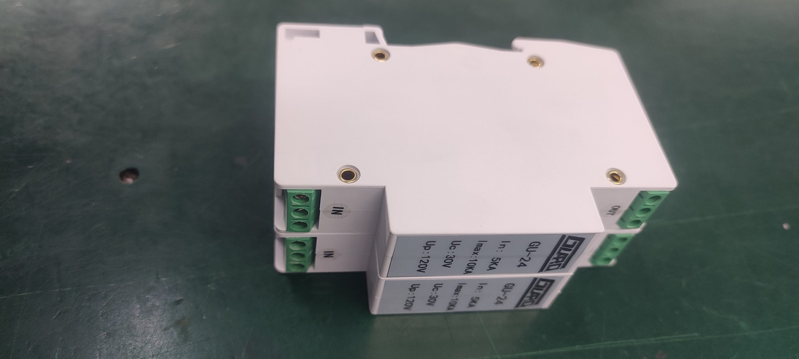
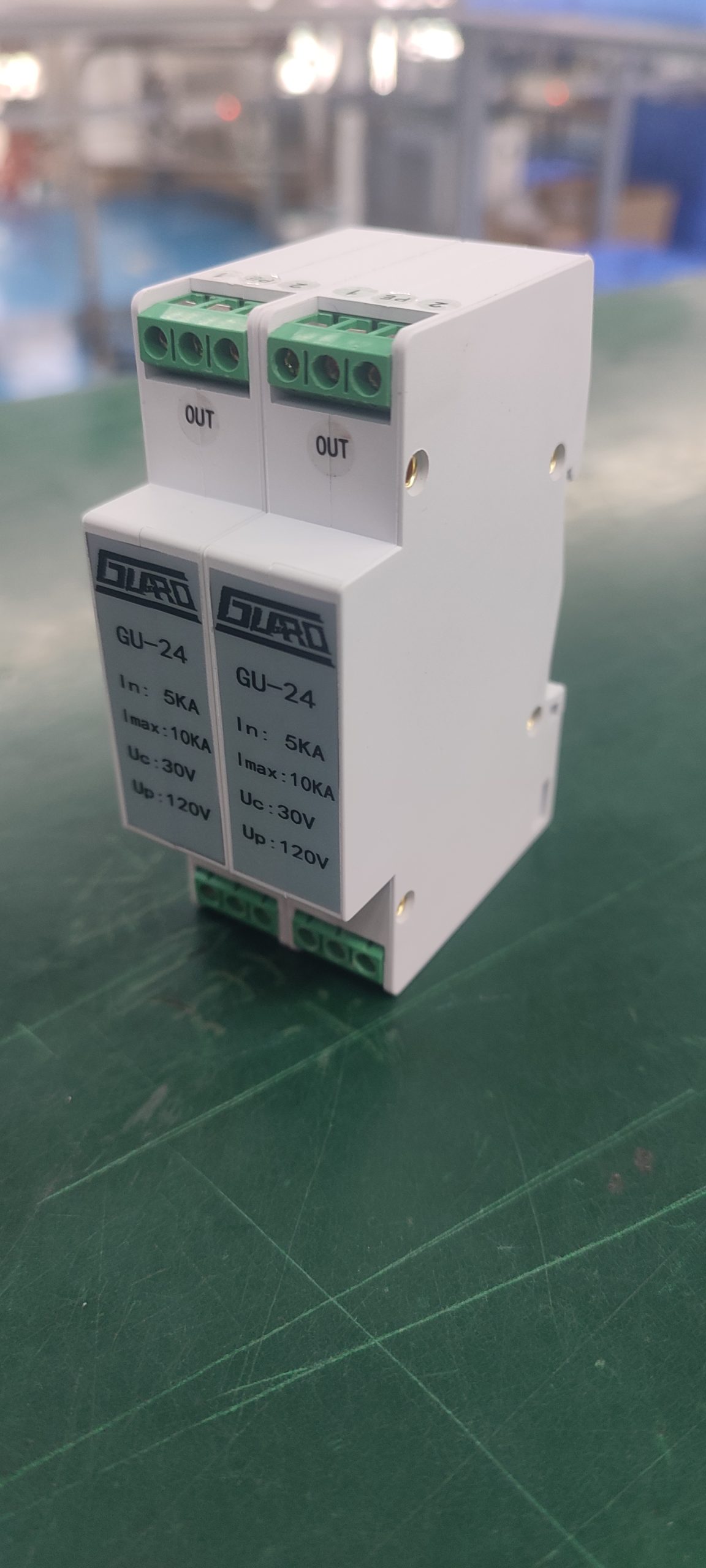
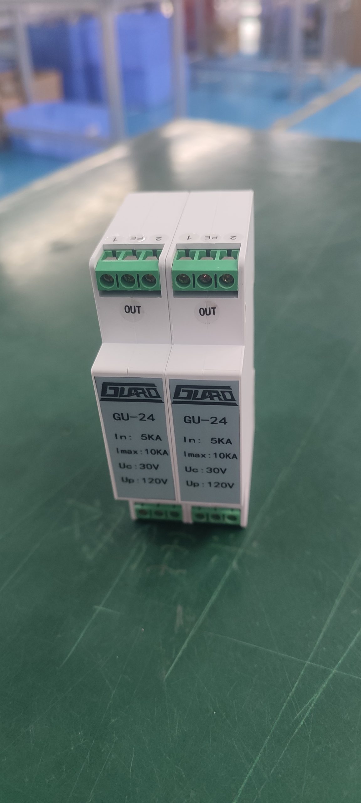
GU-24 Signal Twisted-Pair Surge Protective Device, 24V Un, 18 mm Width
Request a quote
Quality & certifications
Description
The GU-24 is a signal twisted-pair surge protective device in the GU series, intended for surge protection of analog and digital signal communication lines. It is rated for a nominal operating voltage Un of 24V and a maximum continuous operating voltage Uc of 30V, with a voltage protection level Up of ≤120V.
Product Overview
The GU series signal twisted-pair surge protective device is used for surge protection of various analog and digital signal communication lines. The GU-24 variant is the 24V model in this series, which also includes GU-5, GU-12, GU-48, and GU-110 variants. The device is installed directly in series at the front end of the equipment or system being protected.
Key Features
- Nominal operating voltage Un: 24V
- Maximum continuous operating voltage Uc: 30V
- Nominal discharge current In: 5kA
- Maximum discharge current Imax: 10kA
- Voltage protection level Up: ≤120V
- Response time tA: 1ns
- Rated load current IL: 500mA
- Insertion loss: ≤0.5dB/30MHZ
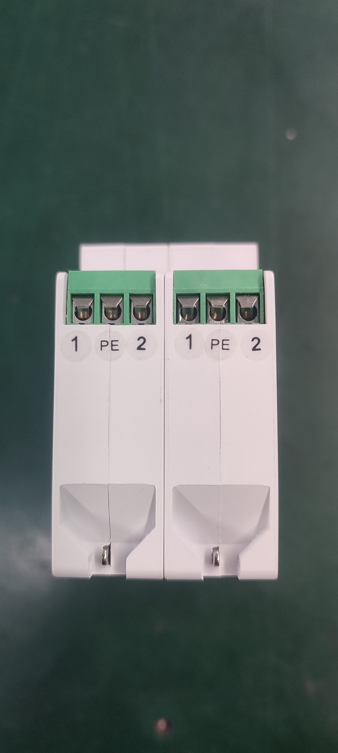
- Screw terminal interface with conductor connection capacity up to ≤2.5mm²
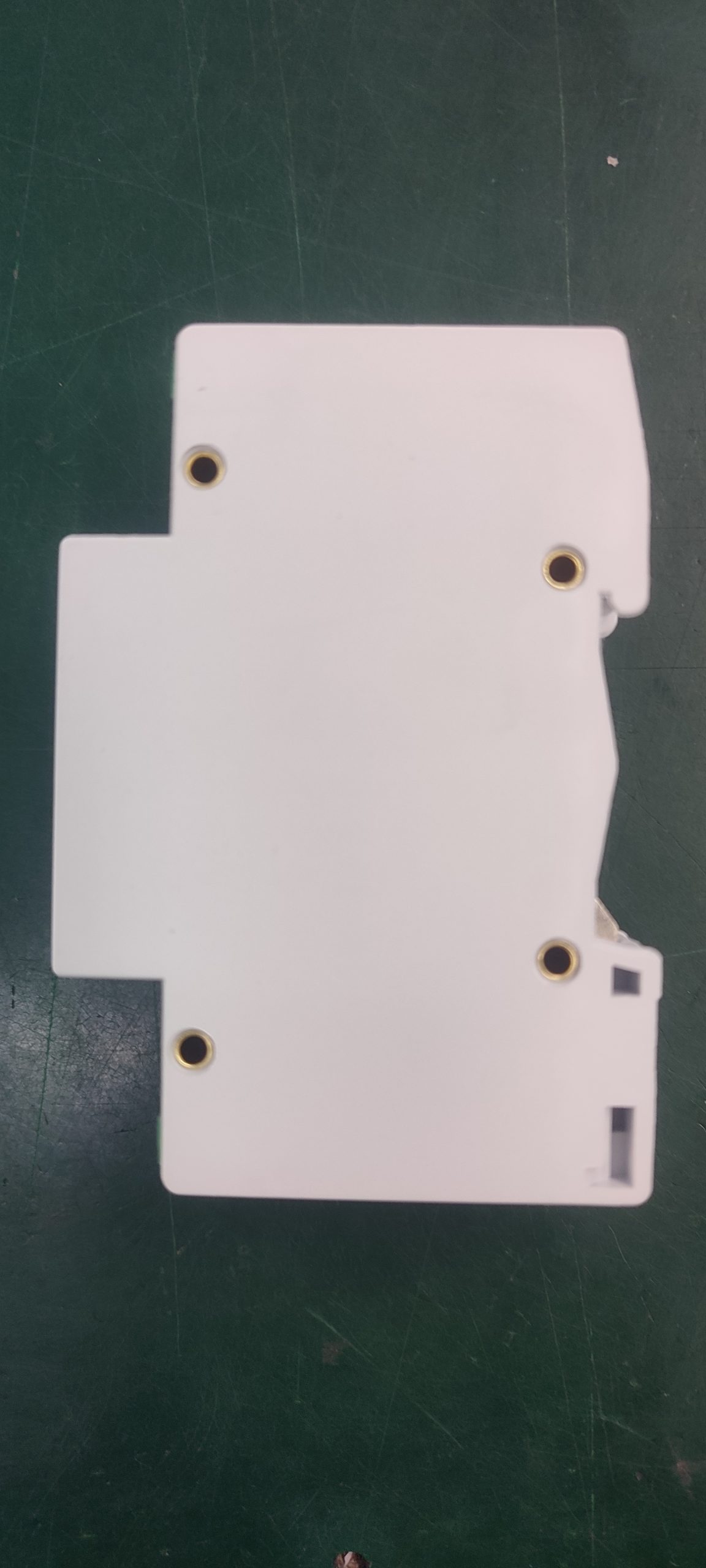
- 35mm DIN rail mounting
- Housing material flame-retardant rating: UL94-V0
- Housing protection rating: IP20
Technical Specifications
| Parameter | Value |
|---|---|
| Model | GU-24 |
| Nominal operating voltage Un | 24V |
| Maximum continuous operating voltage Uc | 30V |
| Nominal discharge current In | 5kA |
| Maximum discharge current Imax | 10kA |
| Voltage protection level Up | ≤120V |
| Response time tA | 1ns |
| Rated load current IL | 500mA |
| Insertion loss | ≤0.5dB/30MHZ |
| Mounting method | 35mm DIN rail |
| Conductor connection capacity | ≤2.5mm² |
| Interface type | Screw terminals |
| Housing material flame-retardant rating | UL94-V0 |
| Housing protection rating | IP20 |
| Temperature and humidity range | -40℃ to +80℃, relative humidity ≤95% |
| Altitude | ≤3000m |
| Main body dimensions | 90mm × 62mm × 18mm |
Applications
The GU-24 is intended for surge protection of analog and digital signal communication lines. It is installed directly at the front end of the equipment or system being protected, and should be positioned as close as possible to that equipment or system.
Installation and Use
- Install the device directly at the front end of the protected equipment or system, as close as possible to it.
- The device can be connected in series as shown in the wiring diagram. For better protection performance, the grounding conductor should be as short as possible, with a total length controlled within 0.5m.
- Connection conductors should be 1–2.5mm² multi-strand copper wire.
- “IN” is the incoming line terminal; “OUT” connects to the protected equipment or system. The two line runs must be laid separately and must not be bundled together, to prevent secondary induction.
- When installed within the specified conditions, the device does not require long-term maintenance; only routine system maintenance is needed. If signal transmission problems occur and normal transmission resumes after the device is replaced, the device has been damaged and requires repair or replacement.
Frequently Asked Questions
What is the nominal operating voltage of the GU-24?
The nominal operating voltage Un is 24V, with a maximum continuous operating voltage Uc of 30V.
What is the voltage protection level of the GU-24?
The voltage protection level Up is ≤120V.
How is the GU-24 mounted?
It is mounted on a 35mm DIN rail and uses screw terminals, with conductor connection capacity up to ≤2.5mm².
How should the grounding conductor be routed?
The grounding conductor should be as short as possible, with a total length controlled within 0.5m.
Related products
-
HSRJ45-100M 24V Two-in-One Network Surge Protective Device with 100 Mbps Signal Path
Request a quote -
GU-220 Signal Twisted-Pair Surge Protective Device, 220V Uc, 18mm DIN Rail
Request a quote -
GUD-110 Signal Twisted-Pair Surge Protective Device, 110V Un, 18 mm Width
Request a quote -
GN-RJ45/1000/POE Signal Surge Protective Device — RJ45, 1000 Mbps, PoE
Request a quote
Reviews
There are no reviews yet.