
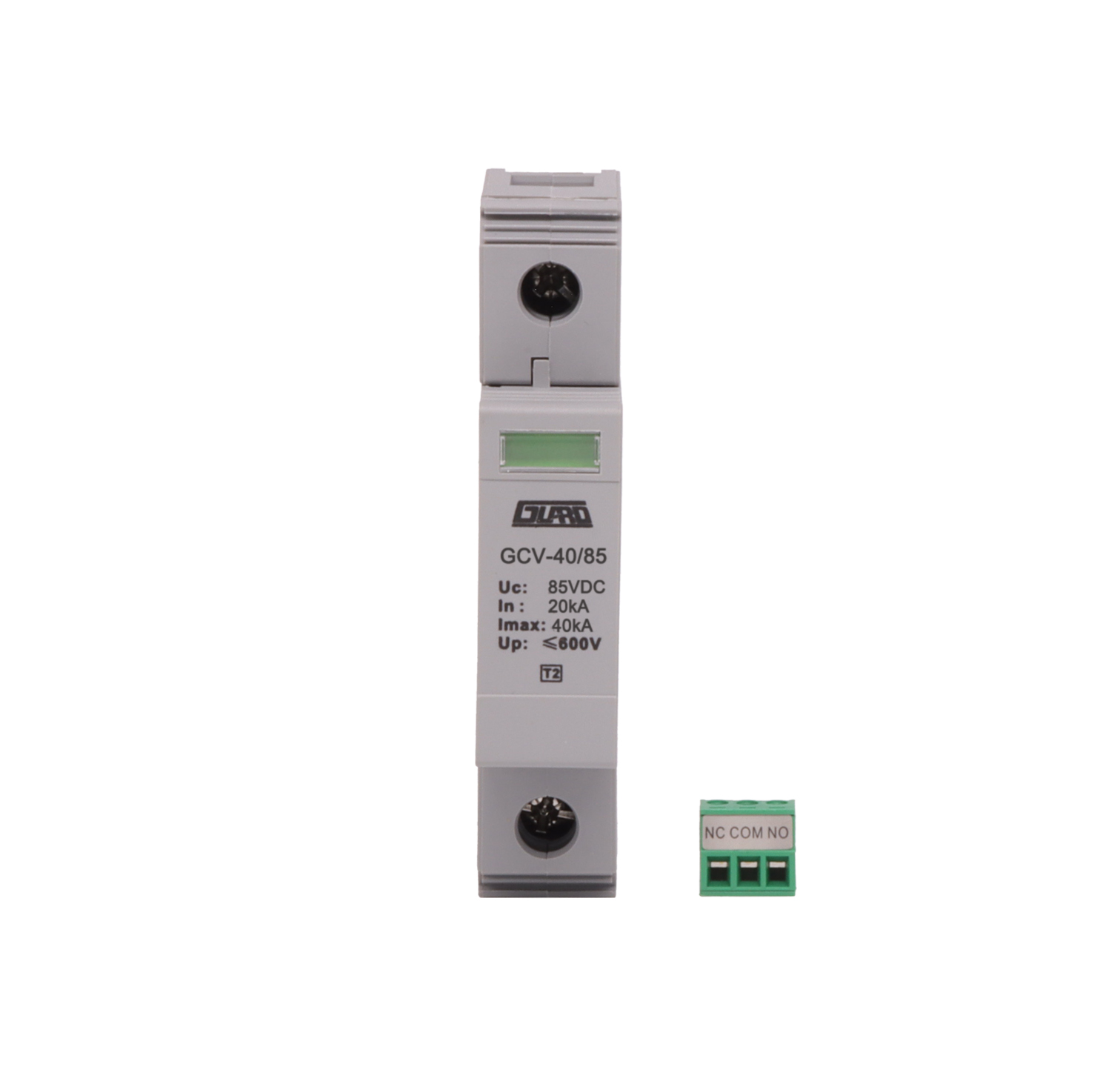
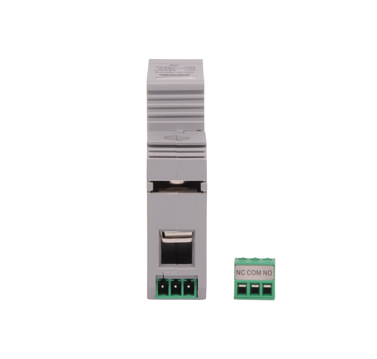

GCV-40-85DC-1-FM DC Surge Protective Device, 85 VDC, 40 kA, with Remote Signaling
Request a quote
Quality & certifications
Description
The GCV-40-85DC-1-FM is a DC surge protective device intended for the second stage (Class C) of lightning and surge protection for DC power systems. It limits surge voltages on DC supply lines and is installed ahead of the equipment being protected.
Product Overview
The device is designed for use in DC power systems and can be installed in LPZ1 or directly inside a distribution cabinet (switch box). It is connected in parallel to the power line and supports three protection modes: V+ to earth, V− to earth and V+ to V−. A status window indicates the operating state: green for normal, red for failed. An optional remote signaling function provides alarm dry contacts.
Key Features
- Second stage (Class C) DC surge protection
- Maximum continuous operating voltage Uc: 85 VDC
- Nominal discharge current In: 20 kA (8/20 µs)
- Maximum discharge current Imax: 40 kA (8/20 µs)
- Voltage protection level Up at In: 600 V
- Response time tA: ≤25 ns
- Protection modes: V+ to earth, V− to earth, V+ to V−
- Green/red failure indication window
- Optional remote signaling: alarm dry contact, NC-COM normally closed, NO-COM normally open
- 35 mm electrical DIN rail mounting
Technical Specifications
| Parameter | Value |
|---|---|
| Model | GCV-40/85DC/1 FM |
| Maximum continuous operating voltage Uc | 85 VDC |
| Nominal discharge current (8/20 µs) In | 20 kA |
| Maximum discharge current (8/20 µs) Imax | 40 kA |
| Voltage protection level (In) Up | 600 V |
| Response time tA | ≤25 ns |
| Protection modes | V+ to earth, V− to earth, V+ to V− |
| Failure indication | Green: normal; red: failed |
| Remote signaling (optional) | Alarm dry contact, NC-COM: normally closed, NO-COM: normally open |
| Backup fuse | 32 Agl/gG |
| Temperature range | −40 °C … +80 °C |
| Installation connection / conductor size | Parallel / stranded 4–16 mm² |
| Remote signaling contact terminal conductor capacity | ≤1.5 mm² |
| Housing material | Reinforced thermoplastic, UL94-V0 |
| Product dimensions | 90 × 65 × 18 mm |
| Mounting method | 35 mm electrical DIN rail |
| Protection degree | IP20 |
Applications
The GCV-40-85DC-1-FM is used for the second stage (Class C) of lightning and surge protection on DC power systems, protecting downstream DC load equipment. It can be installed in LPZ1 or directly in a distribution cabinet (switch box).
Installation and Use
- Inspect the surge protective device before installation. Do not install a device that shows any defect.
- Use the device only within the conditions stated in the technical data. Exceeding the specified upper limits may damage the surge protective device and the protected equipment.
- Installation must follow the relevant standards and specifications for the device and must be carried out by qualified personnel in front of the electronic equipment to be protected.
- The device can be installed in LPZ1 or directly in a distribution cabinet (switch box).
- The device can be fixed on a 35 mm electrical DIN rail.
- Connect the device in parallel to the power line according to the protection mode: V+ to earth, V− to earth, V+ to V−. The copper conductors connected at both ends of the device have a cross-section of 4–16 mm².
- An overcurrent protection device such as an air switch or fuse must be installed ahead of the surge protective device in the circuit.
- Use the shortest possible connecting lines.
- Keep the protected line at a sufficient safe distance from the incoming line and the earth line to avoid secondary induction on the line.
- When installed within the specified conditions, the device does not require long-term maintenance; only routine system maintenance is needed. If the green indicator window turns red during use, the surge protective device is damaged and must be repaired or replaced.
Frequently Asked Questions
What does the status window indicate?
Green indicates normal operation; red indicates that the device has failed and must be repaired or replaced.
What conductor cross-section is used for the main connection?
The parallel connection uses stranded copper conductors of 4–16 mm². The remote signaling contact terminals accept conductors up to 1.5 mm².
What backup fuse is specified?
A 32 Agl/gG backup fuse is specified.
How is the device mounted?
It is mounted on a 35 mm electrical DIN rail.
Related products
-
G1V DC40/75 FM DC Surge Protection Module — Class II, 75 Vdc, 40 kA, Hot-Swappable
Request a quote -
GCV-40-240DC-2FM DC Power Surge Protective Device, Class II, 240 V DC, 40 kA
Request a quote -
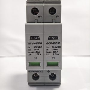
GCV-40/350DC-2-FM DC Power Surge Protective Device, Class II, 350VDC, 40kA
Request a quote -
GCV-40-75DC-1FM DC Power Surge Protective Device, Class II, 75 V DC MCOV
Request a quote
Reviews
There are no reviews yet.