
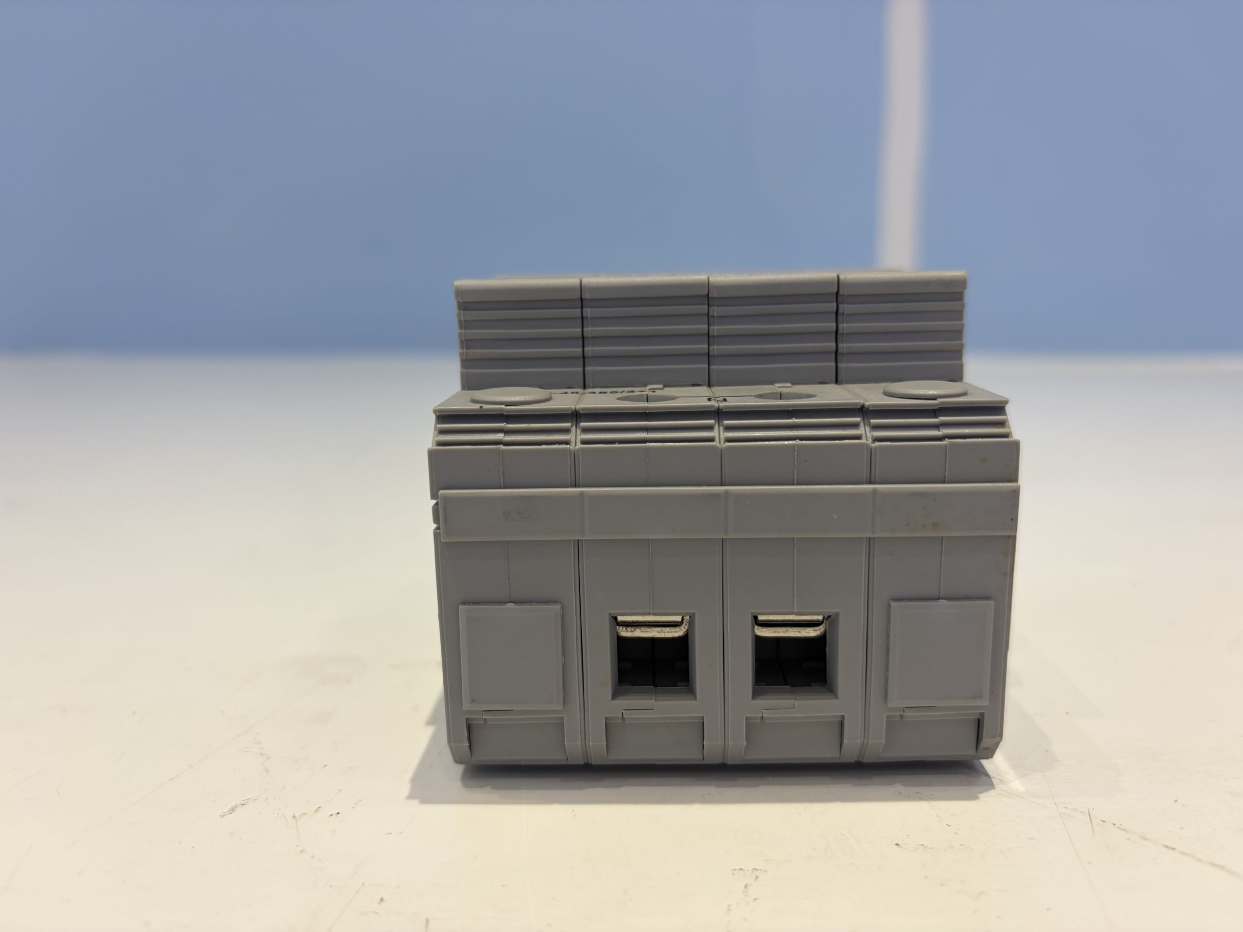
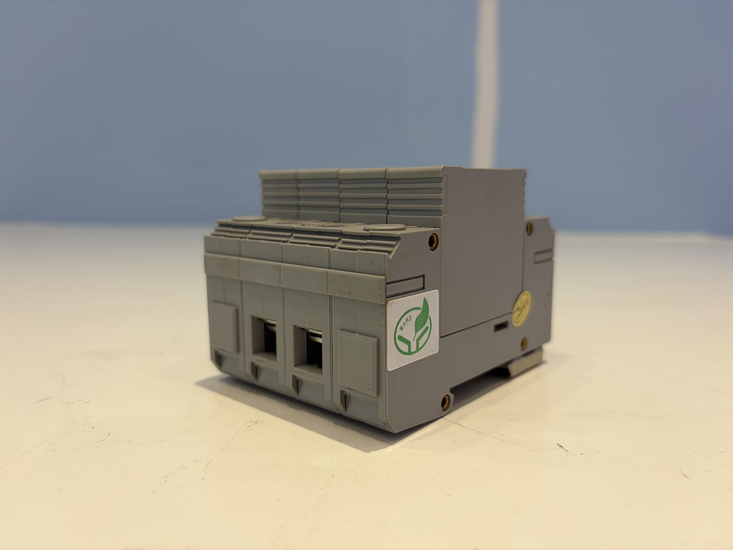
GCV-40-385-3+1 AC Power Surge Protective Device, Class II, 3+1 Configuration
Request a quote
Quality & certifications
Description
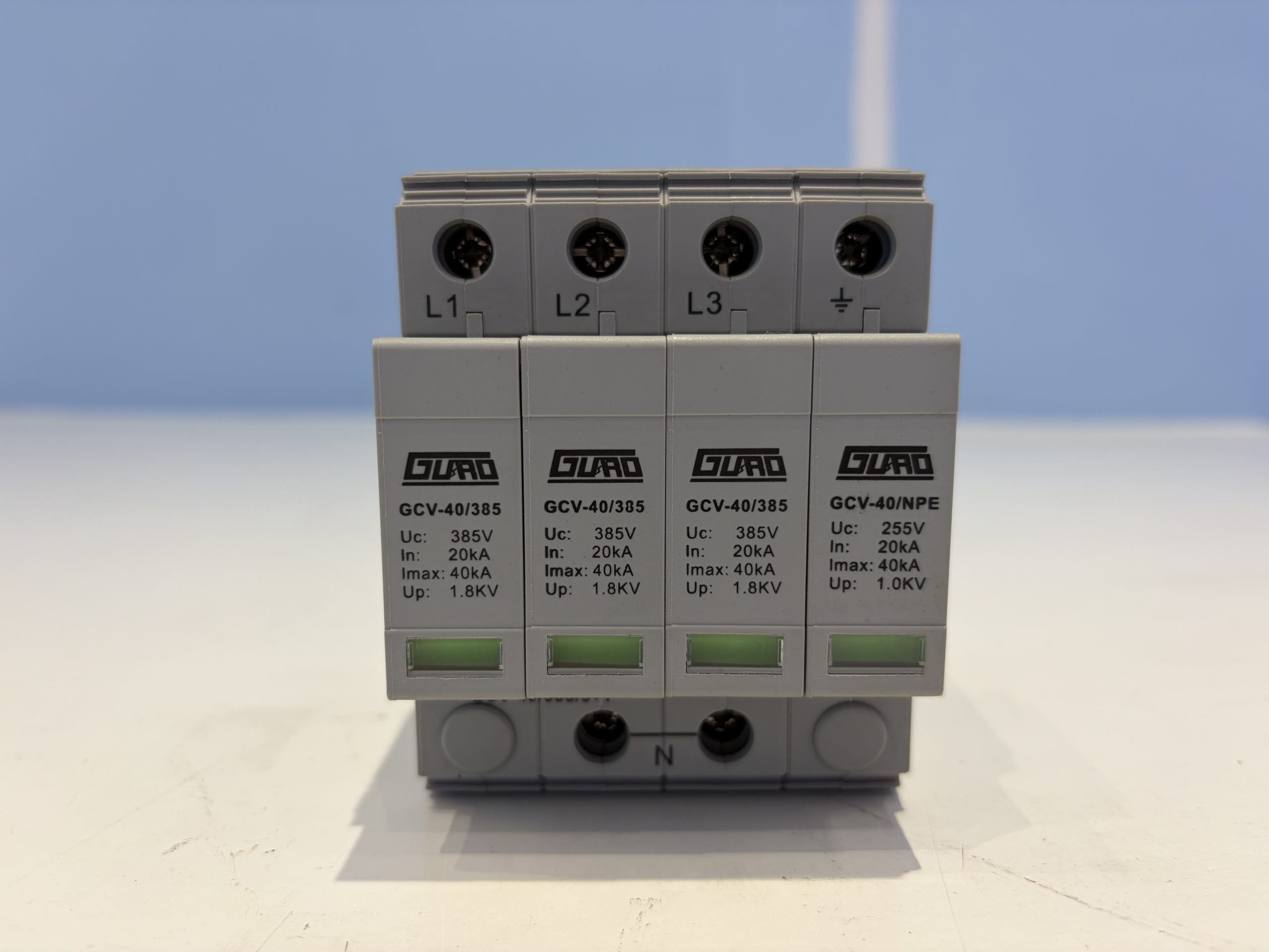
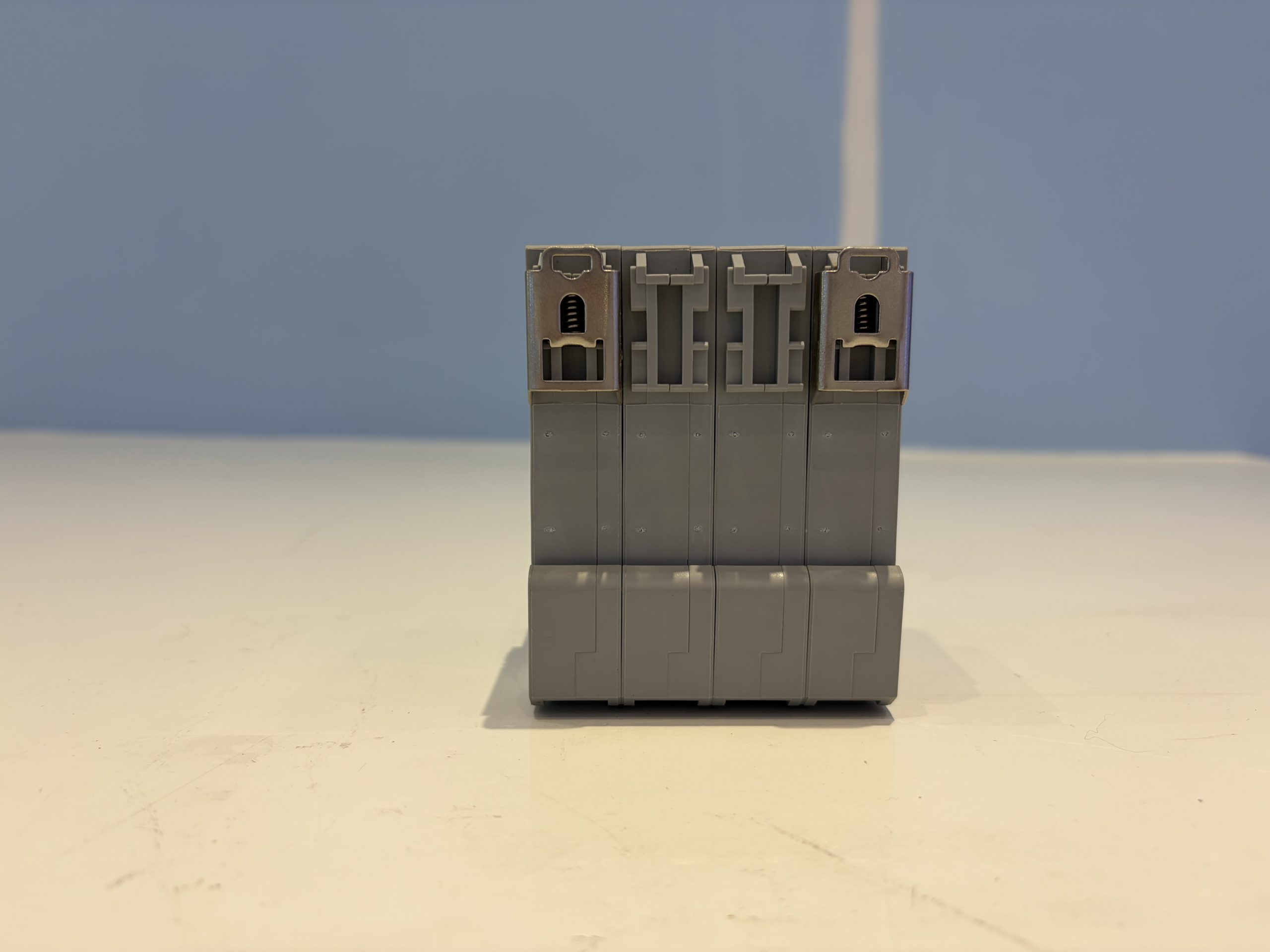
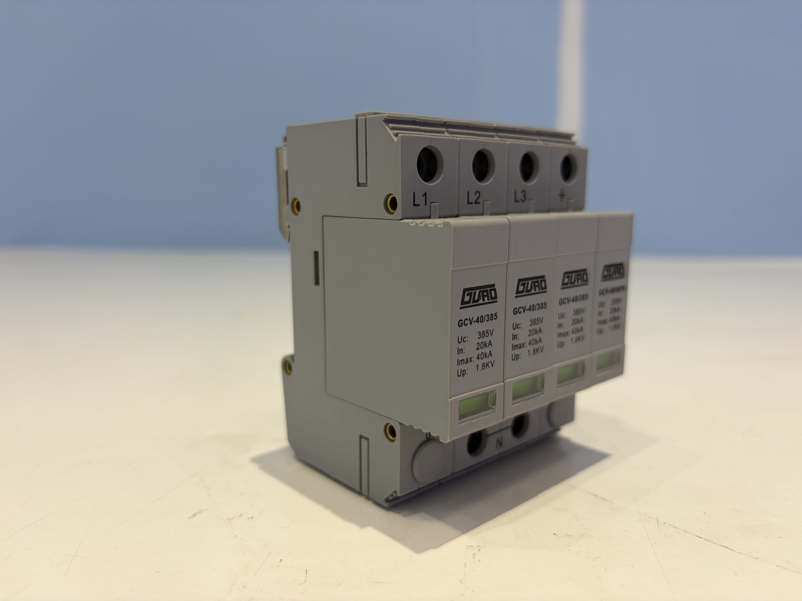
The GCV-40-385-3+1 is a Class II AC power surge protective device intended for lightning overvoltage protection of three-phase AC power supplies. It is configured as a 3+1 arrangement, providing L-N protection and N-PE protection. The device uses a 35mm DIN rail mounting method and includes a status indicator window for monitoring module condition.
Product Overview
The GCV-40-385-3+1 is a surge protective device classified as Class II. It is designed for use on three-phase AC power systems with a nominal operating voltage Un of 220V~. The L-N maximum continuous operating voltage Uc is 385V~, and the N-PE maximum continuous operating voltage Uc is 255V~. The device provides a nominal discharge current In of 20kA and a maximum discharge current Imax of 40kA.
The SPD includes a status indicator for both L-N and N-PE paths. A green indicator shows normal operation, while a red indicator shows that the device has failed. A remote signaling contact is provided as a changeover contact.
Key Features
- Class II surge protective device for three-phase AC power systems
- 3+1 configuration with L-N and N-PE protection
- Nominal discharge current In: 20kA
- Maximum discharge current Imax: 40kA
- L-N voltage protection level Up(In@8/20µs): 1.8kV
- N-PE voltage protection level Up(In@8/20µs): 1.0kV
- L-N response time tA: 25ns
- N-PE response time tA: 100ns
- Status indicator: green for normal, red for failure
- Remote signaling changeover contact
- 35mm DIN rail mounting
- Housing material: PC+PBT with UL94-V0 flame rating
- IP20 enclosure protection
Technical Specifications
| Parameter | Value |
|---|---|
| SPD classification | II |
| Nominal operating voltage Un | 220V~ |
| L-N maximum continuous operating voltage Uc | 385V~ |
| N-PE maximum continuous operating voltage Uc | 255V~ |
| Nominal discharge current In | 20kA |
| Maximum discharge current Imax | 40kA |
| L-N voltage protection level Up(In@8/20µs) | 1.8kV |
| N-PE voltage protection level Up(In@8/20µs) | 1.0kV |
| L-N response time tA | 25ns |
| N-PE response time tA | 100ns |
| L-N, N-PE status indication | Green: normal / Red: failed |
| Mounting method | 35mm DIN rail |
| Conductor connection capacity | ≤25mm² |
| Maximum torque | 3.2Nm~3.7Nm |
| Housing material | PC+PBT |
| Housing material flame rating | UL94-V0 |
| Remote signaling contact type | Changeover contact |
| Remote signaling contact AC performance | 250V/0.5A |
| Remote signaling contact DC performance | 125V/0.2A |
| Enclosure protection rating | IP20 |
| Temperature (humidity) range | -40℃ to +80℃, relative humidity ≤95% |
| Altitude | ≤3000m |
| Main body dimensions | 90mm×65mm×72mm (tolerance ±1 mm) |
Applications
The GCV-40-385-3+1 is intended for lightning overvoltage protection of three-phase AC power supplies. It is suitable for installation in electrical distribution systems where Class II surge protection is required for L-N and N-PE paths.
Installation and Use
The device can be connected using direct parallel wiring or V-shaped wiring as shown in the wiring diagram. For better protection performance with direct parallel wiring, the wiring should be as short as possible, with a total length controlled within 0.5m.
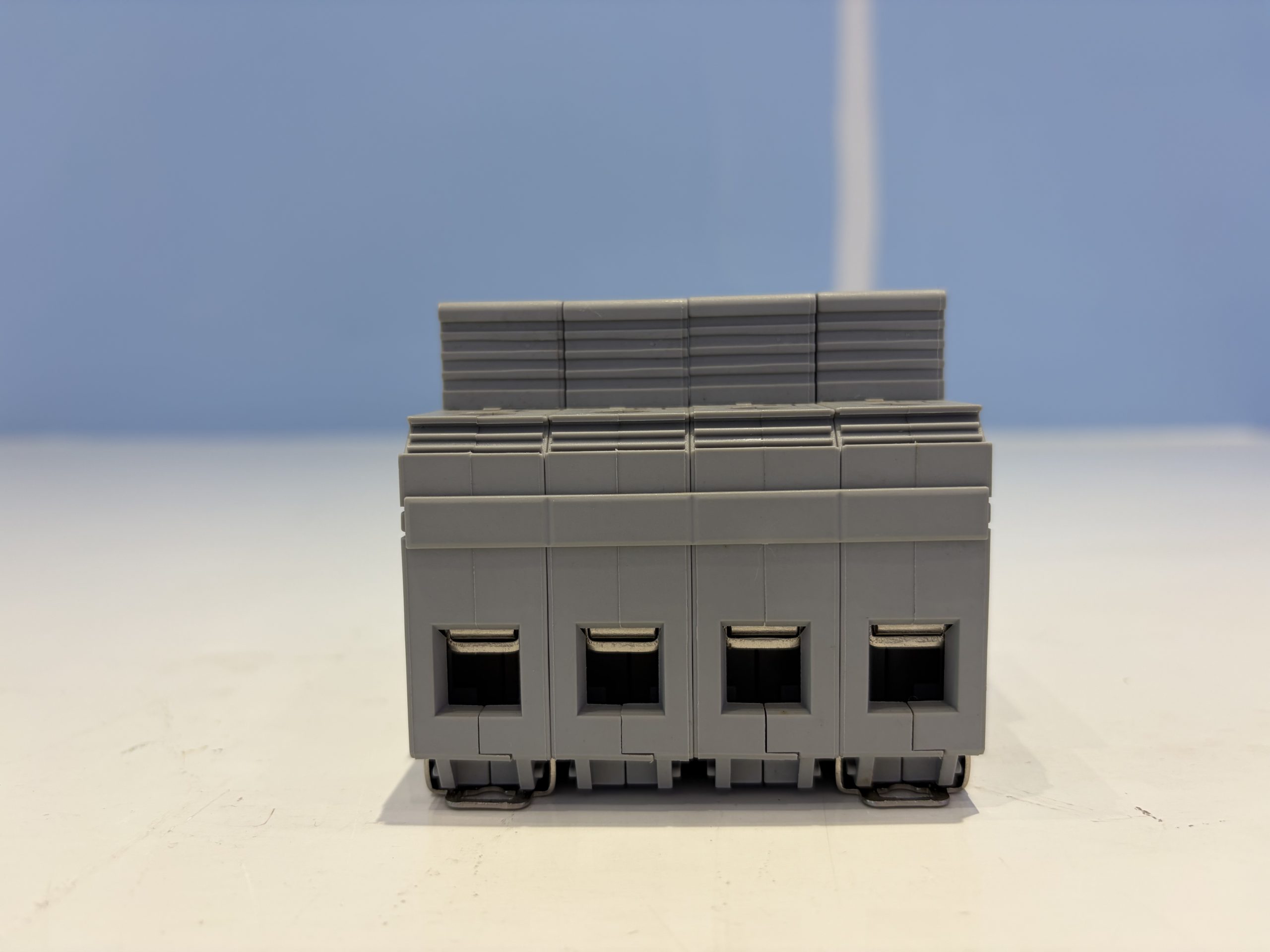
Connecting conductors should be 10-25mm² multi-core copper conductors. A suitable circuit breaker or fuse should be connected in series at the front end of the SPD. The circuit breaker should have a C trip characteristic.
Power must be disconnected during installation. Live operation is strictly prohibited. Connecting conductors must meet the specified requirements.
During normal operation, the status indicator window should be green. When the SPD has failed, the status indicator changes to red. The SPD requires no special maintenance; only regular checks are needed to confirm that the module is not loose and that the status indication is normal.
The SPD can be judged as failed and should be replaced promptly if either of the following occurs: the status indicator turns red, or the alarm dry contact changes to an open circuit state.
Frequently Asked Questions
What does the status indicator show?
The status indicator window shows green during normal operation and red when the SPD has failed.
What conductor size is required?
Connecting conductors should be 10-25mm² multi-core copper conductors. The conductor connection capacity is ≤25mm².
How is the SPD mounted?
The SPD is mounted on a 35mm DIN rail.
What should be done if the SPD fails?
If the status indicator turns red or the alarm dry contact changes to an open circuit state, the SPD has failed and should be replaced promptly.
Related products
-
G1V-60/385/B+C FM Three-Phase AC Power Surge Protective Device, Class II, 60 kA Imax, Hot-Swappable
Request a quote -
GCV-60/385/1+1 Single-Phase AC Power Surge Protective Device, Class II, 60kA Imax
Request a quote -
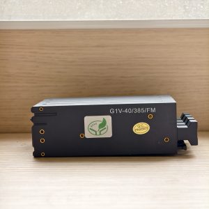
G1V-80/385/B+C FM Three-Phase AC Power Surge Protection Device, Class II, 80 kA Imax
Request a quote -
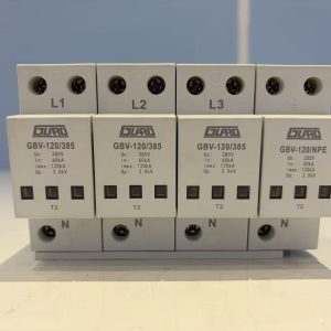
GBV-120-385-3+1 FM AC Power Surge Protective Device, Class II, 3+1 Configuration
Request a quote
Reviews
There are no reviews yet.