
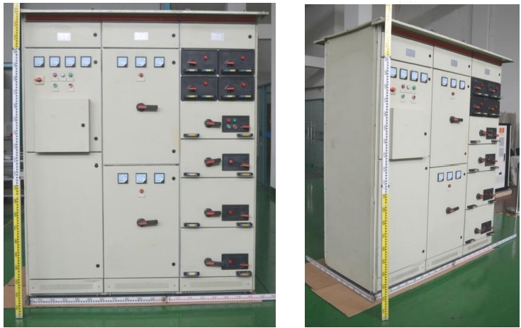
GCK-1600A Low-Voltage Switchgear Assembly, 1600A Rated Current, IP42
Request a quote
Description
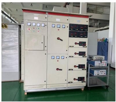
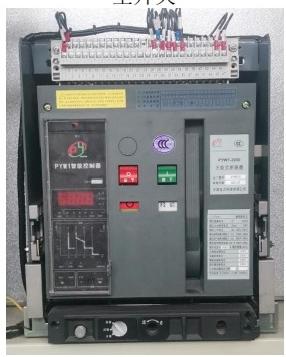
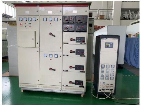
The GCK-1600A is a low-voltage switchgear assembly with a rated current of 1600A, a rated operating voltage of 400V, and a rated frequency of 50Hz. It is a floor-type, indoor, fixed installation assembly built on a bolted C-shaped steel frame, with a main bus running above the cabinet through the full assembly length. The main switch is a universal circuit breaker, and the assembly is configured with feeder and control functional units.
Product Overview
The assembly is composed of a cabinet, universal circuit breaker, moulded-case circuit breakers, AC contactors, thermal overload relays, copper busbars, an N busbar, a PE busbar, PVC insulated conductors, busbar clamps, busbar frames, insulators, insulated support strips, main circuit connectors, and 1/2 unit adapters. The cabinet frame is assembled with C-shaped steel bolts, and internal dimensions, component dimensions, and compartment dimensions follow a module of E=25mm.
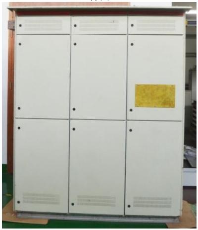
The main bus is located above the cabinet and runs through the entire low-voltage switchgear assembly. The cabinet top is fitted with a top cover, and the universal circuit breaker is fitted with a face mask. The cabinet surface is electrosprayed with light camel epoxy powder. The main switch incoming line mode is the lower inlet line. The control cabinet distribution bus surface is tinned; the other copper busbars, the N busbar, and the PE busbar are bare copper with no surface treatment. Part of the lap surface is pressed to increase the contact area, and some parts have heat-shrink sleeve.
Key Features
- Rated current of the complete equipment: 1600A
- Rated operating voltage: 400V; rated frequency: 50Hz
- Rated insulation voltage: 690V; auxiliary circuit insulation voltage: 400V
- Rated impulse withstand voltage: main circuit 8kV, auxiliary circuit 4kV
- Main bus rated short-time withstand current 30kA (effective value) and rated peak withstand current 63kA
- Enclosure protection grade IP42
- Mechanical impact rating IK10 for the cabinet and door panels, IK05 for functional unit panels, instruments, and indicator light covers
- Internal isolation form of functional units: form 1
- Floor-type fixed installation, indoor use
- Cabinet surface electrosprayed with epoxy powder for corrosion prevention
Technical Specifications
| Parameter | Value |
|---|---|
| Rated voltage Un | 400V |
| Rated operating voltage Un | 400V |
| Rated frequency fn | 50Hz |
| Rated insulation voltage Ui | 690V |
| Auxiliary circuit insulation voltage Ui | 400V |
| Rated impulse withstand voltage Uimp | Main circuit: 8kV; auxiliary circuit: 4kV |
| Overvoltage category | III |
| Electric shock protection type | Class I complete equipment |
| Pollution level of the micro-environment | 3 |
| Electrical clearance | ≥10.0mm |
| Creepage distance | ≥12.5mm |
| Rated current of complete equipment In | 1600A |
| Temperature rise verification method | Method a |
| Main bus rated current, rated short-time withstand current, rated peak withstand current | 1600A, 30kA (effective value) / 63kA (peak value) |
| Feeder cabinet distribution busbar group rated current, rated short-time withstand current, rated peak withstand current | 800A, 30kA (effective value) / 63kA (peak value) |
| Control cabinet distribution bus rated current, rated short-time withstand current, rated peak withstand current | 800A, 30kA (effective value) / 63kA (peak value) |
| Main switch type | Universal circuit breaker |
| Main switch model | PYW1-2000/3P |
| Main switch rated current Inm | 2000A |
| Main switch In, Icu, Ics, Icw | In: 2000A; Icu: 85kA; Ics: 85kA; Icw: 85kA/1s |
| Number of circuits | Feeder cabinet: 2 circuits; control cabinet: 8 loops |
| Feeder cabinet outgoing line rated currents | P1 and P2: 400A and 400A; Icc: 30kA |
| Control cabinet outgoing line rated currents | C1–C8: 40A, 40A, 40A, 40A, 40A, 160A, 160A, 280A; Icc: 30kA |
| Feeder cabinet outgoing line protection devices | P1, P2: In 500A, Icu 100kA, Ics 75kA |
| Control cabinet outgoing line protection devices | C1–C5: In 63A, Icu 85kA, Ics 70kA; C6, C7: In 250A, Icu 85kA, Ics 70kA; C8: In 400A, Icu 100kA, Ics 75kA |
| Rated dispersion factor (RDF) | Feeder cabinet: 1.0; control cabinet: 1.0 |
| Enclosure protection grade | IP42 |
| Mechanical impact rating | IK10 (cabinet, door panels); IK05 (functional unit panels, instruments, indicator light covers) |
| Internal isolation form of functional units | Form 1 |
| Minimum isolation distance for withdrawable components | 20.9mm |
| EMC environment | Environment A |
| Rated power consumption of fuse | / |
| Insulating materials and heat resistance grade | DMC material, epoxy resin material, ABS material, polyethylene, rubber; heat resistance grade E |
| Main busbar specification | TMY 10mm×100mm |
| N busbar specification | TMY 10mm×50mm |
| PE busbar specification | TMY 5mm×50mm |
| Feeder cabinet distribution bus | 10mm×60mm |
| Control cabinet distribution busbar | 6mm×80mm |
| PVC insulated conductor | BVR 16mm², 2.5mm² |
| Cabinet dimensions (height × width × depth) | 2200mm × 600mm × 800mm |
| Front door panel thickness | 2.0mm |
| Rear door thickness | 1.5mm |
| Cabinet shelf thickness | 2.0mm |
| Cabinet material | Steel |
| Function unit panel material | ABS |
| Maximum mass of the prototype | 872kg / 1 set (3 tower) |
| Main ground screw | M12 iron galvanized |
| Maximum insulation support distance, main busbar | 600mm (horizontal) |
| Maximum insulation support distance, feeder cabinet distribution busbar | 530mm (vertical) |
| Maximum insulation support distance, control cabinet distribution busbar | 700mm (vertical) |
| Maximum insulation support distance, neutral busbar | 600mm (horizontal) |
Applications
The GCK-1600A is intended for indoor, floor-type fixed installation as a low-voltage switchgear and controlgear assembly. The feeder cabinet and control cabinet outgoing line circuits are configured for distribution load and motor load. The assembly is not intended for use in photovoltaic facilities.
Installation and Use
The assembly is installed as a floor-type fixed installation and is intended for indoor use. The main switch incoming line mode is the lower inlet line, and the main switch wiring mode is bottom wiring or top wiring. The inlet and outlet line of the sample cabinet is the back line of the incoming cabinet, the feeding cabinet, and the control cabinet.
The electrical connection mode of the functional units is FFF for the incoming cabinet and feeder cabinet and WWW for the control cabinet. In this notation, the first letter indicates the electrical connection type of the main incoming line circuit, the second letter indicates the electrical connection type of the main outgoing line circuit, and the third letter represents the electrical connection type of the auxiliary circuit; F denotes fixed connection, D denotes separable connection, and W denotes removable connection.
For protection grounding, the cabinet is equipped with a grounding bus TMY 5mm×50mm with a contact site and grounding sign. The door and the cabinet are connected by a BVR 2.5mm² yellow-green two-color line, so that the whole cabinet forms a complete grounding protection circuit. The main ground screw is M12 iron galvanized. Corrosion prevention is provided by electrostatic spraying of epoxy powder on the cabinet surface, and other metal parts have corrosion prevention ability.
The prototype lifting structure consists of a cabinet top lifting ring and bottom assembly channel steel, and the prototype lifting method is 1 set (3 units) overall lifting.
Frequently Asked Questions
What is the rated current of the GCK-1600A assembly?
The rated current of the complete equipment is 1600A, with a rated operating voltage of 400V and a rated frequency of 50Hz.
What are the main bus short-time and peak withstand currents?
The main bus is rated 1600A with a rated short-time withstand current of 30kA (effective value) and a rated peak withstand current of 63kA.
What is the enclosure protection grade?
The enclosure protection grade is IP42. The cabinet and door panels have a mechanical impact rating of IK10, while functional unit panels, instruments, and indicator light covers have IK05.
How is the assembly installed?
It is a floor-type fixed installation intended for indoor use, with the main switch incoming line mode being the lower inlet line.
Related products
-
GP-CZ-3000 Secondary AC Power Distribution Cabinet for Station Power Systems
Request a quote -
90210016 Optical-Electrical Hybrid Box for RRU Power and Fiber Distribution
Request a quote -
GDZ-125A-20 Bottom-Mounted Power Distribution Cabinet, 19-Inch Rack, 125 A Input, 20 Output Breakers
Request a quote -
90210017 Fiber Optic Distribution Box — IP65 Wall-Mount and Pole-Mount Enclosure with 36 LC SM Terminations
Request a quote
Reviews
There are no reviews yet.